|
|
|
|
|
|
|
|
|
|
|
ผู้ชม
|
|
|
วันนี้
|
67
|
|
เมื่อวาน
|
113
|
|
ทั้งหมด
|
392,049
|
|
|
|
|
ชมหน้าอื่นๆ
|
|
|
วันนี้
|
68
|
|
เมื่อวาน
|
122
|
|
ทั้งหมด
|
461,108
|
|
|
|
|
|
|
|
|
|
|
|
|
|
|
|
|
|
|
|
|
|
|
|
HENRY Tech
กายแอ็ทเซส เป็นผู้นำเข้า และจำหน่ายอะไหล่-อุปกรณ์ระบบทำความเย็น henry tech จาก USA. ซึ่งสินค้ายี่ห้อนี้ได้รับการยอมรับจากทั่วโลก ถึงคุณภาพและความปลอดภัย วาล์วทุกตัวของยี่ห้อนี้ได้ผ่านการรับรองอย่างถูกต้อง
 
|
PRESSURE RELIEF VALVES
|
|
|
|
- Brass construction set and sealed at the factory; all N.P.T.F. connections are American Standard dry-seal tapered pipe threads
- Valves are stamped with catalog number, size, pressure setting, capacity and ASME-UV National Board symbol; CRN number and flow arrow
- All N.P.T.F. connections are American standard dry-seal tapered pipe threads
- Consistent operation at marked pressure setting
- These relief valves are designed with HENRY’S “Center Loading Pivot” concept allowing the piston to reseat squarely to the body seat, thus reducing the possibilities of leakage
- Suitable for refrigerants R22, R134a, R404a, R410a, R500, R502 and other industrial fluids non-corrosive to brass, monel, steel, Neoprene and Teflon.
- Factory set and sealed
- Temperature rating: –20°F to +160°F
- Orders must specify catalog number, pressure setting, and type of refrigerant or fluid with which the valve is to be used; UV/NB certified setting range varies with design, see ratings sheet; contact Henry for non-certified setting
range info.
Selection of Relief Valves. Most states and municipalities which have refrigeration safety codes conform to the “American Standard Safety Code for Mechanical Refrigeration (ANSI/ASHRAE 15).” This code and ASME states a relief valve setting is not to exceed the design working pressure of the vessel on which the relief valve is installed. The discharge capacity required is based on the size of the vessel and the refrigerant used. The discharge capacity of relief valves varies with the pressure setting. The capacities of Henry Relief Valves at various pressure settings are available by calling the Engineering and Technical Assistance line 1-800-627-5148. Whenever conditions permit it is highly advisable to have the relief valve pressure setting (which must not exceed the design working pressure of the vessel) at least 25% higher than the normal maximum operating pressure for the
refrigerant used.
Standard pressure settings (brass): 150, 235, 300, 350, 400, 450 PSIG
Standard pressure settings (steel): 150, 250, 300 PSIG
Standard pressure settings (High Pressure): 500, 550, 600, 650, 675 PSIG
Important: Orders must specify pressure setting.
Certification: Available if requested on purchase order, (-C) suffix, i.e. 5600-300-C
Relief Valve Capacity Ratings: (Pounds per minute) - Henry Relief valves are constructed and marked in accordance with the requirements of the ASME (Boiler and Pressure Vessel Code Section VIII, Division 1). These valves are also approved by many local refrigeration and air conditioning codes in the USA and Canada for relief of excess pressure. In addition, these valves are stamped with the ASME UV symbol and NB to indicate National Board certification as to capacities. | |
|
|
* Suitable for Ammonia
Features:
-
Bodies: 5600 Series, Ductile Iron; 5300 Series, Stainless Steel; 5200 Series, Brass
-
Seat inserts, seat discs and main guides, piston stainless steel on 5600 series
-
Seat material: Teflon® or Neoprene
-
Connections: (NPTF) pipe threaded
-
Other component metal parts are steel
-
Set and sealed at the factory and furnishedwith nameplates stamped with catalog no., size, pressure setting, capacity and ASMEUV National Board symbol
-
Temperature rating: -20°F (-28°C) to +160°F (+71°C)
-
Protective lacquer finish on 5600 series
-
*Suitable for ammonia, HFC’s and CFC’s, refrigerants and other industrial fluids
non-corrosive to steel and Teflon as indicated
-
Each valve has unique serialization for tagging requirements |
|
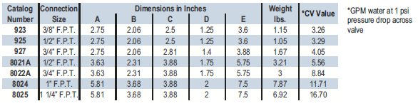
3-WAY DUAL SHUT-OFF VALVES
|
|
Features:
92 Series: forged brass;
802 series: forged steel; painted
450 PSI (31.0 Bar) Steel 6
75 PSI (46.6 Bar) Brass
Steel -20°F (-29°C) to +300°F (+149°C)
Brass –40°F (-40°C) to +300°F (+149°C)
-
Recommended for use with relief valve types
-
92 series is suitable for refrigerants and other industrial fluids non-corrosive to steel and brass
-
802 Series is suitable for refrigerants including ammonia and other industrial fluids non-corrosive to steel
On all vessels 10 ft³ and larger when relief valves are used as the over pressure protective device, a dual relief valve assembly is required. Three-Way Dual Shut-off Valve inlets are shown at the bottom of the illustration. Tight shut-off can be obtained at either extreme of stem position, closing off either the left or right outlet port. The system should not be run with the valve stem in the center position. A dual relief valve installation consists of one three-way shut-off valve and two relief valves so arranged that both relief valves cannot be shut off from the protected pressure vessel at the same time. This permits safe removal of either relief valve for repair or replacement, while the vessel is protected and under pressure. Each relief valve must have sufficient capacity to provide the necessary discharge flow when used alone.
The design of this Three-Way Valve provides full discharge area through the valve regardless of stem position, assuring maximum protection. Furthermore, this design provides for convenient parallel mounting of the two relief valves and fulfills the requirement set forth in the ANSI/ASHRAE 15. “No stop valve shall be located between any automatic pressure relief device or fusible plug and the part or parts of the system protected thereby, except when the parallel relief devices are so arranged that only one can be rendered inoperative at a time for test or repair purposes.” Two three-way valves, installed in a drier bypass arrangement, permit installation or removal of service drier without air, dirt, or moisture entering line.
| |
|
|
|
|
|
|
|
|
|
|
|
|
|
|
|
|
|
|
|
|
|
|
|
|
|
|
|


Item No : 7771
NEEDLE VALVE
|
|
|
|
|
|
|
|
|
|
|
|
Item No : 7772
NEEDLE VALVE
|
|
|
|
|
|
|
|
|
|
|
|
Item No : 7773
NEEDLE VALVE
|
|
|
|
|
|
|
|
|
|
|
|
Item No : 7774
NEEDLE VALVE
|
|
|
|
|
|
|
|
|
|
|
|
SAFETY VALVES
|
|
|
|
|
|
|
|
|
|
|
|
SIGHT GLASSES "AC&R"
|
|
|
|
|
|
|
|
|
|
|
|
THREE-WAY DUAL
|
|
|
|
|
|
|
|
|
|
|
|
|
|
|
|
|
|
|
|
|
|